实干、实践、积累、思考、创新。
ETABS/SAP2000中的截面切割Section Cut功能非常强大,可以利用截面切割抓取任意位置的内力。
这个功能有时候很有用,比如在做局部节点有限元分析时,可以利用Section Cut捕获一些复杂区域的外力输入。
但需要注意Section Cut输出的内力方向。以下内容整理自官方文档(https://docs.csiamerica.com/help-files/sap/Output/Section_Cut_Output_Conventions.htm)。
Section Cut Output Conventions
Section cut forces are reported at a single point in the local coordinate system defined for the section cut.
截面切割内力以其局部坐标系形式输出,并切是以单点合力的形式输出,在该点一共输出六个不同的内力分量。
Six different force components are reported at that single point. They are:
-
- F1: A force in the section cut local 1-axis direction. 沿截面切割局部 1 轴方向的力。
- F2: A force in the section cut local 2-axis direction. 沿截面切割局部 2 轴方向的力。
- F3: A force in the section cut local 3-axis direction. 沿截面切割局部 3 轴方向的力。
- M1: A moment about the section cut local 1-axis. 绕截面切割局部 1 轴的力矩。
- M2: A moment about the section cut local 2-axis. 绕截面切割局部 2 轴的力矩。
- M3: A moment about the section cut local 3-axis. 绕截面切割局部 3 轴的力矩。
Section cut forces are reported as forces acting on the objects that make up the group that defines the section cut. An example of this is described below. Positive section forces act in the same direction as the positive section cut local axes. The sense of positive moments can be determined using the right-hand rule.
截面切割内力为作用于构成定义该截面切割的组的对象上的力。下文描述了一个示例。正的截面力方向与截面切割局部坐标轴的正方向一致。正力矩的方向可使用右手定则确定。
Consider the example shown in the figure below. The global coordinate system axes and the section cut local coordinate system axes are shown in Figure a. This illustrates that the local coordinate system axes may be different from the global system.
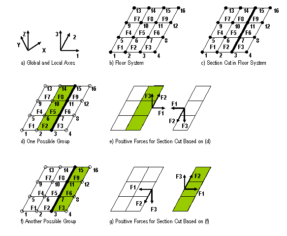
Figure b shows a floor system that consists of 9 area objects labeled F1 through F9 and 16 associated point objects labeled 1 through 16. Suppose that we want to determine the section cut forces through the floor system at the location identified by the heavy line in Figure c. This section cut passes through the point objects labeled 3, 7, 11 and 15.
Two groups can be defined for use in the section cut definition. Figure d shows the first possible group, which includes area objects F2, F5 and F8 and point objects 3, 7, 11 and 15. Figure e shows free body diagrams that define the positive direction of section cut forces when the section cut is defined using the group definition shown in Figure d. Note that the positive section cut forces acting on the left free body diagram are in the same direction as the positive section cut local axes shown in Figure a. The left free body diagram is the one that includes the objects that were used to define the group that defined the section cut.
Figure f shows the second possible group that could define the section cut. This group includes area objects F3, F6 and F9 and point objects 3, 7, 11 and 15. Figure g shows free body diagrams that define the positive direction of section cut forces when the section cut is defined using the group definition shown in f. Note that the positive section cut forces acting on the right free body diagram are in the same direction as the positive section cut local axes shown in Figure a. The right free body diagram is the one that includes the objects that were used to define the group that defined the section cut.
总结:
(1)截面切割内力以其局部坐标系形式输出,且以单点合力的形式输出。该点包含六个内力分量
(2)截面切割输出的力作用于定义该截面切割的组内对象之上,可视为该截面切割隔离体所受的外力。
(3)截面切割输出的力始终与事先定义的局部坐标轴正方向一致,无论用于定义截面切割的组位于截面哪一侧。
关于我们
超限复杂高层结构设计 | 美标欧标结构设计| 软件定制开发| 环评减振控制 |人行及风致振动控制 | 减隔震设计 | 施工过程模拟 | 小品钢结构 | 有限元仿真分析 | BIM与GH参数化 | 大震弹塑性分析

https://www.jdcui.com
合作及技术咨询
COOPERATION & CONTACT
E-mail:jidong_cui@163.com
